How Suspension Bridges Carry Load: Cables, Towers, and Anchors Explained
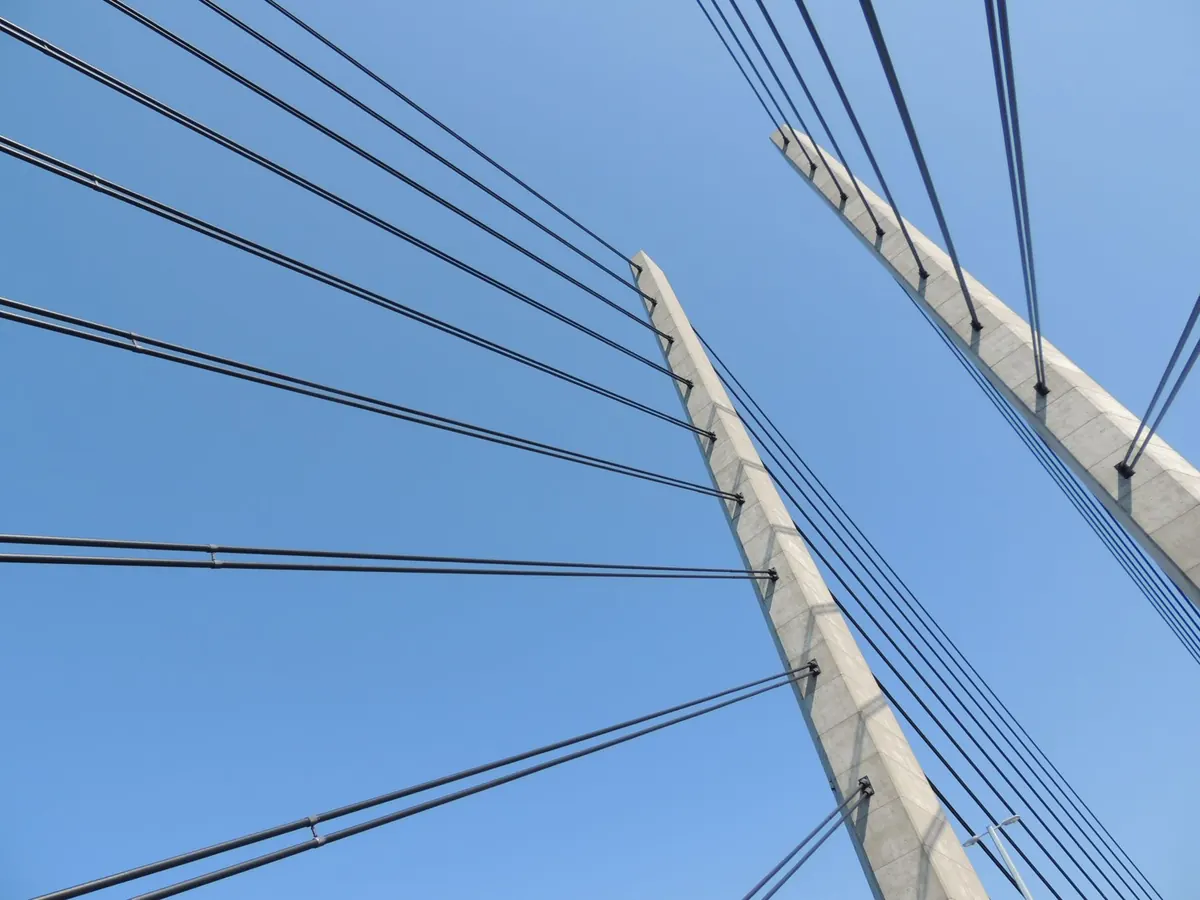
Stand near the base of a large suspension bridge on a breezy day and the movement is oddly gentle: the deck sways a few centimetres, the cables hum, and nothing appears to be holding anything up. Then a loaded lorry crosses and the structure answers — the deck dips, the hangers tighten, the main cable shifts its curve by a fraction. That small visible response is the end of a long conversation between steel and gravity, and following it from the road surface to the ground is the best way to understand the bridge.
The load path, step by step
Every suspension bridge, from a park footbridge to the Humber Bridge, runs on the same five-part arrangement. Follow a single wheel load from the moment it rolls onto the deck:
- The deck takes the wheel load and spreads it into the stiffening girder or truss beneath the road surface.
- The hangers pick that load up at regular intervals and carry it vertically to the main cables.
- The main cables gather those small vertical pulls and turn them into one large tension force running along the curve.
- The towers receive the cable at the top and pass the vertical share down into the foundations.
- The anchorages take the horizontal pull — the part that would otherwise drag the towers toward each other — and lock it into rock or a mass of concrete.
Two things are worth noticing here. Almost every element works in either pure tension or pure compression, which is why suspension bridges are so efficient: bending is kept to a minimum wherever possible. And the load never takes a shortcut. Nothing in the deck is strong enough to span the gap alone, and nothing needs to be.
The main cable: geometry doing the heavy lifting
A main cable is a rope in the oldest sense, just built at an unusual scale. On the largest bridges it is spun in place by a travelling wheel that drags each wire across the span; thousands of wires are bundled into strands, and the strands into a cable perhaps a metre across.
A cable cannot push, only pull, so it settles into whatever shape lets it carry the load in tension alone. Under its own weight that shape is a catenary. Under a deck hung from closely spaced hangers — effectively a uniform load — it is very nearly a parabola, and that is the curve engineers use for calculations. The result is a beautifully simple relationship: H = wL²/8f, where H is horizontal tension, w the load per metre, L the span and f the sag. Double the span and the tension roughly quadruples at the same sag.
Why sag is a design decision, not an accident
That formula explains the profile of every suspension bridge you have seen. A shallow cable is economical in tower height and cable length, but the tension becomes enormous. A deep sag eases the tension but demands taller towers, more cable and steeper approaches. Most long-span road bridges land somewhere around a span-to-sag ratio of nine to twelve, which is a compromise rather than a rule of nature.
Tension is not constant along the cable, either. The horizontal component stays the same everywhere, but the vertical component grows as the cable steepens, so tension peaks at the top of the tower. That is where the cable is thickest and where the saddles are built for their heaviest service.
Towers: standing in compression
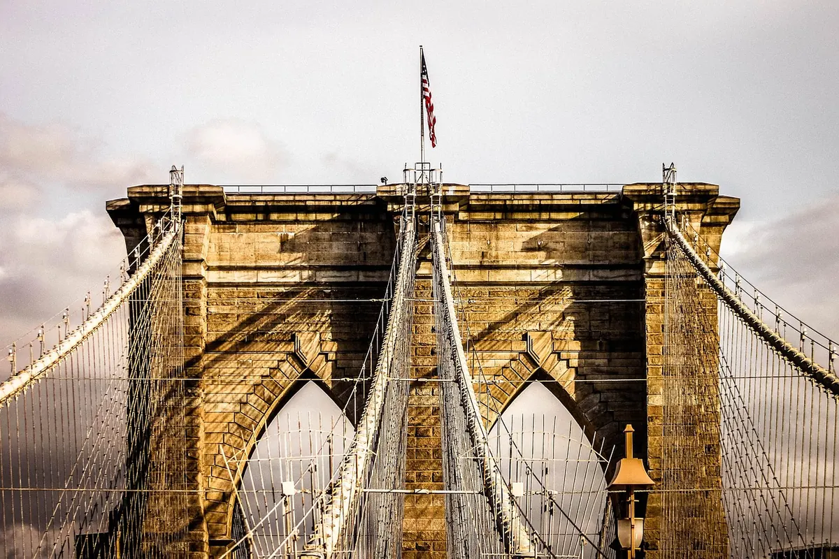
A tower is a column, and columns are happiest in compression. All the vertical load collected by the cables arrives at the saddles and runs down the legs to the foundations. In the ideal case, nothing exotic happens.
The awkward part is imbalance. Live load is rarely symmetric: a queue of lorries on one side span and nothing on the other pulls the tower top sideways and puts it into bending. Some bridges answer this with very stiff towers; many modern designs do the opposite, using slender legs, often with a crossbeam, that flex enough to shed the bending into the cable and the deck. Watch the top of a tower on a busy bridge and you may see movement measured in centimetres.
Three details repay attention on any tower: the saddle, where the cable passes over and may slide or be clamped; the bearings and expansion joints beneath the deck, which let the span breathe with temperature and traffic; and the foundations, whether caissons sunk into a riverbed or spread footings on rock.
Hangers, deck and the stiffening girder
Hangers look like the least important parts of the bridge. They are usually slender wire ropes or steel rods spaced a few metres apart, and each carries only a small share of the total load. But they decide how evenly the cable is fed, and their spacing sets the size of the local bending in the deck between them.
Most hangers hang vertically. A few notable bridges use inclined hangers arranged in overlapping triangles, which adds damping and helps control oscillation. Either way, each one is a tension member with a fatigue life, and inspecting the sockets is part of the routine work that keeps a bridge honest.
The deck is a beam, not a basket
The stiffening girder — a truss on older bridges, a streamlined steel box on newer ones — has three jobs. It spreads a heavy concentrated load across several hangers instead of dumping it on one. It carries loads applied between hangers. And it gives the span torsional stiffness so that wind cannot twist the deck into a destructive rhythm. That last point is not theoretical: the 1940 Tacoma Narrows failure came from a deck that was too flexible in torsion and too willing to absorb energy from the wind.
If you want one sentence to remember about the deck, make it this: the cables carry the bridge, and the deck makes the cables behave.
Anchors: where the pull disappears into the ground
At each end, the main cable dives into the ground, and that is where much of the drama actually sits. The anchor must resist the horizontal pull of the cable at its full working tension, which on a long span is measured in thousands of tonnes. There are three common ways to do it:
- Gravity anchors: vast blocks of concrete or masonry whose weight and friction hold the cable. Practical where the ground is firm and space is available.
- Rock anchors: the cable splays into strands grouted into tunnels or deep rock sockets, using the ground itself as the anchor block.
- Tunnel and buried anchorages: the cable runs into a chamber and is fixed to a steel frame tied back into the hillside.
Whatever the type, the anchorage is where a tension force becomes a push on the earth. It is also why suspension bridges need good ground at both ends: the towers can stand in a river, but the anchors cannot. A suspension bridge is really two anchored cables with a road hung between them — the towers only hold the cables up long enough to be useful.
Reading a suspension bridge in person
Next time you are near one, spend five minutes looking at it the way an engineer would.
- Check the sag-to-span ratio. A shallow curve means high tension and efficient towers.
- Find the anchorages. Their size tells you how much horizontal force the ground is being asked to hold.
- Note the hanger spacing and whether they are vertical or inclined.
- Look for expansion joints at the towers and the deck ends; they show where the structure is allowed to move.
- Watch the towers under traffic. A little movement is design, not damage.
None of this replaces a proper inspection, but it makes the structure legible. Load paths stay invisible until you know the sequence: deck, hanger, cable, tower, anchor. Once you have it, a suspension bridge stops looking like a magic trick and starts looking like a very long, very carefully balanced argument with gravity.
Photo: Pixabay / Pexels